
DT FAQ: How to build a Digital Twin w/ MBSE + ModSim + AI?
How to build a Digital Twin with MBSE + ModSim + AI?
FAQ Variant(s): How to build a Digital Twin?
[Kobryn 2017] Digital Twin vs. Physical Twin Equivalency Test
"A reasonable litmus test for a Digital Twin is analogous to the Turing Test for AI. Let:
- ST = System Tester
- PS = Physical System
- PT = Physical Twin representation of PS
- DT = Digital Twin of PT
- V&V-TS = robust Verification & Validation Test Suite shared by PT and DT
If ST executes V&V-TS against both PT and DT, but cannot reliably distinguish DT from PT with probability greater than 80%, then DT is a bona fide Digital Twin of PT:
P(ST correctly distinguishes DT from PT | V&V-TS) <= 0.80— Cris Kobryn, Founder & CTO, PivotPoint Technology Corp. (2017)
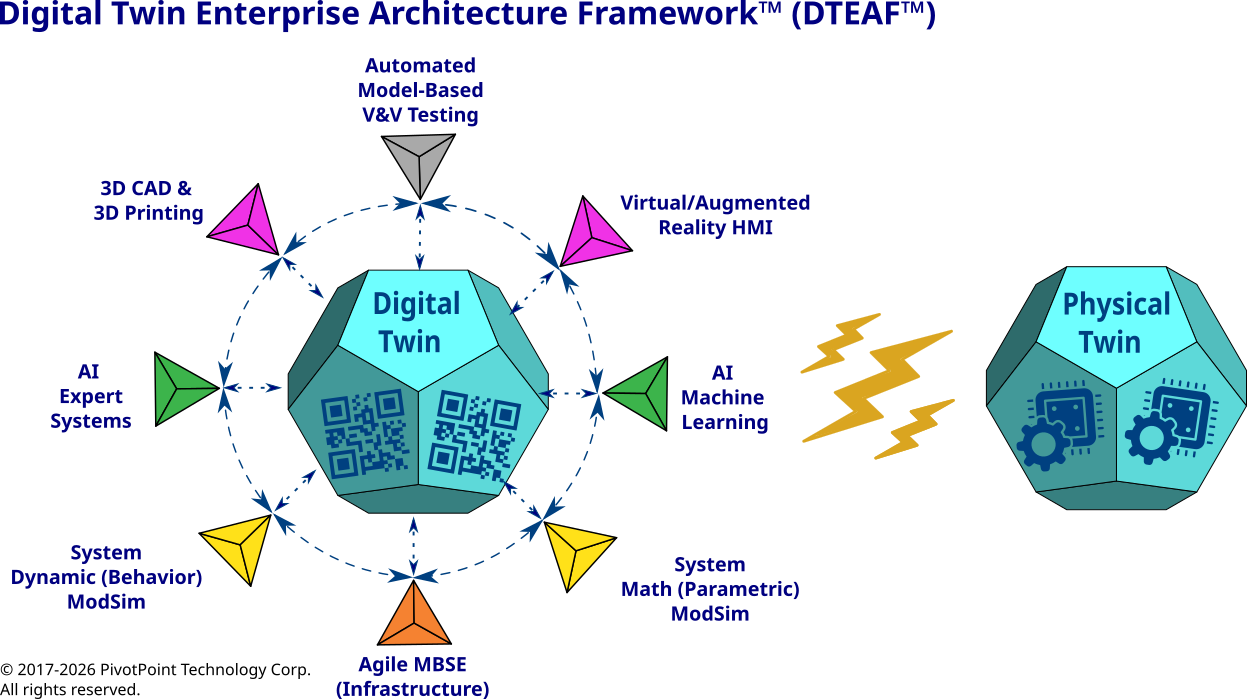
Digital Twin Enterprise Architecture Framework™ (DTEAF™)
Algorithm: Build a Digital Twin Using MBSE + ModSim + AI
REF: Digital Twin vs. Physical Twin Test [Kobryn 2017]
1. Define Physical Twin Scenario
Let PT represent PS in one of two scenarios.
A. To-Be-PT-Scenario
- Neither PT nor PS initially exists.
- A System Requirements Specification (SRS) exists or is developed.
- DT and PS are developed concurrently.
B. As-Is-PT-Scenario
- PS exists.
- PT and DT do not initially exist.
- SRS and Test Cases (TCs) are desirable but not required.
- DT is reverse engineered from PS and available artifacts.
Let:
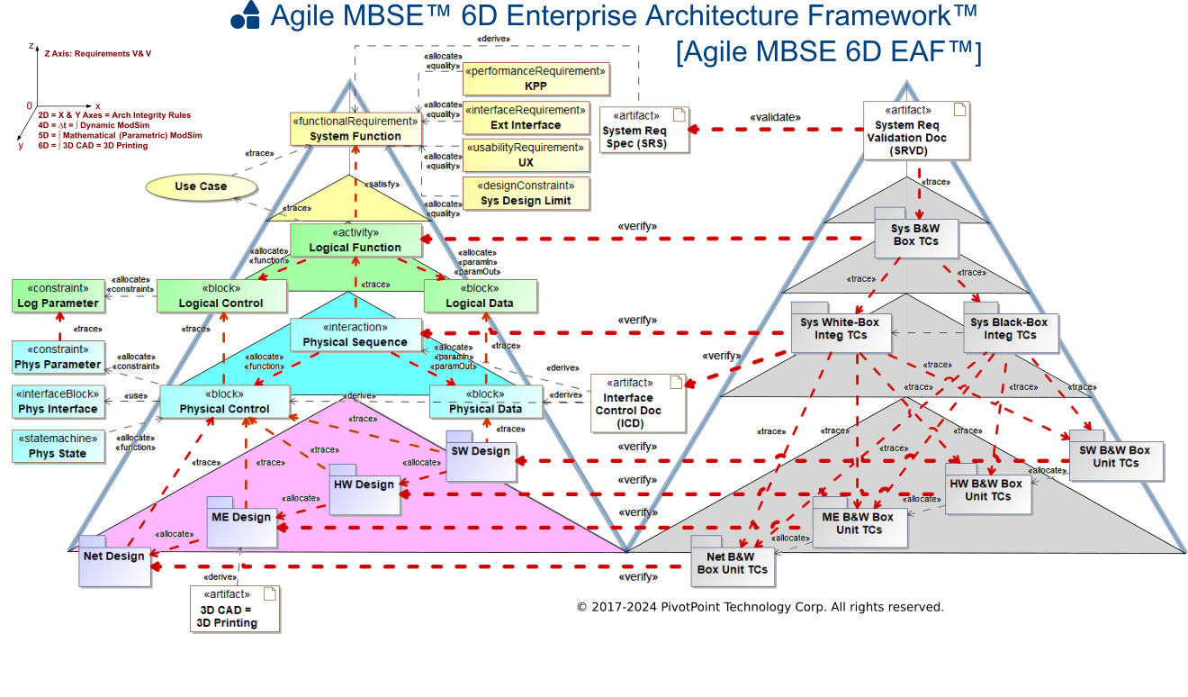
- 6D-EAF-Patterns = PivotPoint Agile MBSE 6D Enterprise Architecture Framework architecture, analysis, and design patterns.
- FOPL = First-Order Predicate Logic representation of 6D-EAF-Patterns.
- ModSim = executable behavioral and mathematical models.
- Target-Tool = MBSE + SysML + ModSim environment, such as Cameo Systems Modeler + Cameo Simulation Toolkit.
2. Bootstrap Digital Twin
IF Scenario = To-Be-PT-Scenario:
- Apply GenAI to SRS, related engineering artifacts, and applicable 6D-EAF-Patterns.
- Generate candidate SysML architecture, Dynamic Behavioral ModSims, Mathematical Parametric ModSims, initial TCs, and requirement-model-test traceability.
- Validate generated content against FOPL constraints, engineering rules, and human subject-matter review.
- Deploy result to Target-Tool.
OUTPUT = BOOTSTRAPPED-DT-To-Be
ELSE IF Scenario = As-Is-PT-Scenario:
- Collect available PS evidence: observations, telemetry, interfaces, source code, drawings, manuals, maintenance data, and optional SRS and TCs.
- Apply GenAI + analytical AI to infer system structure, functions, states, interactions, interfaces, equations, parameters, requirements, and TCs.
- Generate a reverse-engineered SysML + ModSim representation.
- Validate inferred content against observed PS behavior, FOPL constraints, and human subject-matter review.
- Deploy result to Target-Tool.
OUTPUT = BOOTSTRAPPED-DT-As-Is
3. Establish Shared DT/PT Baseline
Create or reconstruct:
- SRS
- shared TCs
- common input/output definitions
- common acceptance criteria
- configuration baseline
- DT <-> PT <-> Requirement <-> TC traceability
For each TC define:
TC = {
    Initial-State,
    Inputs,
    Stimuli,
    Environment,
    Expected-Behavior,
    Expected-Outputs,
    Timing,
    Tolerance,
    Pass-Fail-Criteria
}
The same logical TC shall execute against both DT and PT, using adapters only where physical and digital interfaces differ.
4. Incremental and Iterative DT Development
Develop DT and PT through:
PROTOTYPE -> ALPHA -> BETA -> GENERAL AVAILABILITY
For each Lifecycle-Stage:
Execute shared TCs against DT and, when available, PT.
Compute DT/PT discrepancy:
Delta = Distance(Output-DT, Output-PT)
Measure state, timing, parametric, sequence, distribution, and failure-response errors.
Identify highest-value fidelity gaps.
Recursively refine ModSims:
Macro -> Meso -> Micro
Where:
- Macro = system and mission behavior.
- Meso = subsystem and interface behavior.
- Micro = component, algorithm, and physical behavior.
Refine Dynamic Behavioral ModSims:
- SysML ACT diagrams
- SysML STM diagrams
- SysML SD diagrams
Refine Mathematical Parametric ModSims:
- SysML PAR diagrams
- physics equations
- performance constraints
- reliability and degradation models
- resource, timing, cost, mass, power, and capacity models
Apply AI to:
- generate and refine models
- estimate parameters
- detect anomalies
- identify missing requirements
- generate regression TCs
- diagnose DT/PT discrepancies
Calibrate DT using PS data:
theta* = arg min[Distance(DT(theta), PS)]
Validate with data not used for calibration.
Update DT, PT, SRS, TCs, assumptions, and tolerances while preserving configuration, provenance, and traceability.
Repeat until Lifecycle-Stage exit criteria are satisfied.
5. Synchronize DT and PT
For each approved PT configuration:
DT.Configuration := PT.Configuration
Synchronize as required:
- hardware
- software
- firmware
- interfaces
- parameters
- calibration
- operating state
- maintenance state
- degradation state
- environment
Synchronization may be offline, periodic, event-driven, near-real-time, or real-time.
For multiple physical assets:
DT = {DT-1, DT-2, ..., DT-n}
Each DT-i represents one serialized PS instance. A common DT-Prototype represents the system class.
6. Digital Twin Acceptance Test
When PT exists, execute a blinded DT-vs.-PT test.
For randomized trials i = 1...N:
- Select either DT or PT.
- Execute TC-i.
- Present results to ST without source identity.
- Require ST classification as DT, PT, or Indeterminate.
Compute:
P-correct = Correct-Classifications / Classifiable-Trials
IF P-correct > 0.80:
- DT fails the Kobryn Digital Twin Test.
- Identify discriminating observables.
- Return to Macro -> Meso -> Micro refinement.
ELSE:
- DT passes for the tested scope, configuration, and operating envelope.
Passing is valid only if TCs are robust, nominal and off-nominal behaviors are covered, independent validation data are used, DT outputs are not artificially filtered, and statistical confidence is sufficient.
7. Continuous Digital Twin Evolution
After GA:
- Synchronize DT and PT.
- Monitor
Delta(DT, PT). - Detect configuration, data, model, and AI drift.
- Recalibrate when Delta exceeds tolerance.
- Re-execute regression TCs.
- Revalidate and reaccredit after material change.
Top-Level Pseudocode
Build-Digital-Twin(
    Scenario,
    SRS,
    PS,
    TCs,
    6D-EAF-Patterns
):

    IF Scenario = To-Be-PT-Scenario:

        DT <- GenAI-Forward-Engineer(
            SRS,
            6D-EAF-Patterns,
            FOPL
        )

    ELSE:

        DT <- AI-Reverse-Engineer(
            PS,
            SRS,
            TCs,
            6D-EAF-Patterns,
            FOPL
        )

    Deploy(DT, Target-Tool)

    {SRS, TCs, Traceability}
        <- Establish-Shared-Baseline(DT, PS)

    FOR Stage IN {
        PROTOTYPE,
        ALPHA,
        BETA,
        GENERAL-AVAILABILITY
    }:

        REPEAT:

            Execute(TCs, DT)

            Execute(TCs, PS)
                where PS exists

            Delta <- Compare(DT, PS)

            Refine(
                DT,
                Macro -> Meso -> Micro
            )

            Calibrate(DT)
            Verify(DT)
            Validate(DT, PS)

            Update(
                SRS,
                TCs,
                Traceability
            )

        UNTIL Stage-Exit-Criteria-Pass

    IF PS exists:

        WHILE P-correct > 0.80:

            Refine(DT)
            Recalibrate(DT)
            Revalidate(DT)

    Accredit(DT)

    WHILE PS is operational:

        Synchronize(DT, PS)
        Monitor(DT, PS)

        Recalibrate-Revalidate-Reaccredit
            as required

RETURN DT
DIGITAL TWIN WORKS, DIGITAL TWIN ENTERPRISE ARCHITECTURE FRAMEWORK, DTEAF, AGILE MODEL-BASED SYSTEMS ENGINEERING, AGILE MBSE, and AGILE MBSE 6D EAF are trademarks of PivotPoint Technology Corporation. All other product and service names mentioned are the trademarks of their respective companies.